
To set up a dial gauge and magnetic stand, clamp the gauge in the shortest, stiffest arm position, keep the plunger in line with the movement you want to measure, push it in about one full needle turn, then zero the bezel. Keep any tilt under 10 degrees. At that angle the error is about 1.5%.
The best setup depends on the job. Checking shaft runout, surface flatness and part alignment each need a slightly different arm position. This guide covers the 8 setup steps, the angle rule, two worked examples and the mistakes that ruin readings. To learn the dial itself, see our guide on how to read a dial indicator.
What a Dial Gauge and Magnetic Stand Do Together
A dial gauge (also called a dial indicator) shows very small plunger movements on a round dial. A magnetic stand is a steel base with a switchable magnet and an adjustable arm that holds the gauge. Together they let you measure runout, flatness and alignment without holding the gauge by hand.
Most stands have the same five parts. Knowing each one helps you fix problems later.
| Part | What it does |
|---|---|
| Magnetic base | Grips steel or cast iron when the magnet is switched on |
| Arm and joints | Lets you move the gauge and lock it in place |
| Stem clamp | Holds the gauge by its round stem |
| Plunger and contact point | Touches the surface and moves in and out |
| Bezel | The turning ring you use to set zero |
Step-by-Step: How to Mount a Dial Gauge on a Magnetic Stand
Follow these 8 steps in order. Each one removes a common source of error.
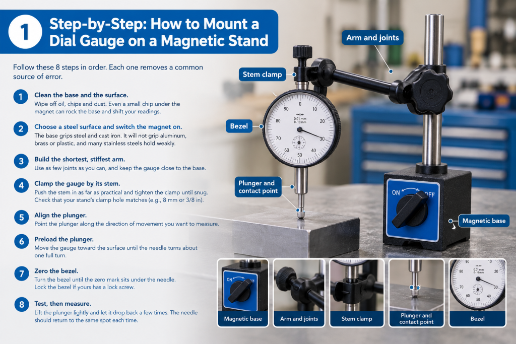
- Clean the base and the surface. Wipe off oil, chips and dust. Even a small chip under the magnet can rock the base and shift your readings.
- Choose a steel surface and switch the magnet on. The base grips steel and cast iron. It will not grip aluminum, brass or plastic, and many stainless steels hold weakly or not at all. After switching on, push the base gently to confirm it is held firmly. Switch the magnet off before you lift the base, since strong bases can pinch fingers.
- Build the shortest, stiffest arm. Use as few joints as you can, and keep the gauge close to the base. A long arm bends slightly, and that bend shows up on the dial.
- Clamp the gauge by its stem. Push the stem in as far as practical and tighten the clamp until snug. Do not overtighten, because a squeezed stem can make the plunger stick. Many gauges have an 8 mm (about 5/16 in) or 3/8 in stem. Check that your stand’s clamp hole matches.
- Align the plunger. Point the plunger along the direction of movement you want to measure. The next section shows why.
- Preload the plunger. Move the gauge toward the surface until the needle turns about one full turn. This lets the gauge read movement in both directions and keeps it from running out of travel.
- Zero the bezel. Turn the bezel until the zero mark sits under the needle. Lock the bezel if yours has a lock screw.
- Test, then measure. Lift the plunger lightly and let it drop back a few times. The needle should return to the same spot each time. If it does, you are ready.
Get the Angle Right: Cosine Error
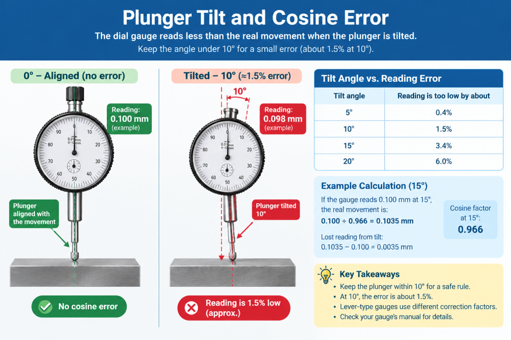
If the plunger is tilted away from the direction you are measuring, the dial shows less than the real movement. This is called cosine error. The tilt angle sets how big the error is.
| Tilt angle | Reading is too low by about |
|---|---|
| 5° | 0.4% |
| 10° | 1.5% |
| 15° | 3.4% |
| 20° | 6.0% |
Example: a plunger gauge tilted 15° reads 0.100 mm (0.0039 in). The real movement is about 0.100 ÷ 0.966 = 0.1035 mm (0.0041 in). That is 0.0035 mm of lost reading from tilt alone.
For tiny movements, 10° or less is a safe rule. Lever-type gauges (see our guide on what a dial test indicator is) follow different correction factors. Check your gauge’s manual for those.
Worked Example 1: Checking Shaft Runout
Runout is how much a shaft wobbles as it turns. Here is a simple check using your stand on a steel bed.
- Set the stand on a steel surface and follow the 8 setup steps.
- Aim the plunger at the center line of the shaft, at a right angle to its surface.
- Preload about one needle turn, then zero at the 0° position.
- Turn the shaft by hand one full turn and read at four points.
| Shaft position | Reading (mm) |
|---|---|
| 0° | 0.00 |
| 90° | +0.03 |
| 180° | +0.05 |
| 270° | −0.03 |
- Subtract the lowest from the highest: 0.05 − (−0.03) = 0.08 mm. That is about 0.0031 in. This total spread is called total indicator reading, or TIR.
Worked Example 2: Quick Flatness Comparison
You can use the same setup to compare heights across a steel plate. This is a quick shop check. It is not a formal flatness test, which needs a surface plate and a set method.
- Place the plunger on a point at one end of the plate and zero the dial.
- Slide the gauge slowly to three more points and note each reading.
- Readings: 0.00, +0.02, +0.05, +0.01 mm.
- Highest minus lowest: 0.05 − 0.00 = 0.05 mm (about 0.002 in).
Why Real Results Differ From the Ideal
A perfect setup does not exist. These factors move your numbers.
You can check your own setup in three quick tests:
- Stability test. Zero the gauge. Gently tap the base and press the arm. If the needle moves more than one graduation and does not come back, the setup is flexing.
- Repeat test. Lift and release the plunger five times. The needle should return to the same mark.
- Known-size test. Zero on a flat steel surface, then slide in a gauge block of known thickness. The dial should match it within the gauge’s stated accuracy.
Common Mistakes With a Dial Gauge Magnetic Stand
These five-minute fixes solve most bad readings.
- Long arm stick-out. Keep the gauge as close to the base as you can.
- Dirty magnet face. Wipe the base each time you move it.
- Overtightened stem clamp. Snug is enough. If the plunger drags, loosen it.
- Tilted plunger. Keep the angle under 10°.
- No preload. Without it, the gauge can run out of travel or skip small movements.
- Moving the stand after zeroing. Re-zero every time the base moves.
- Reading from the side. Look straight at the dial to avoid parallax.
Final Thoughts
Good readings come from a stiff, clean, short setup with the plunger in line with the movement. Take two minutes to run the stability and repeat tests before you trust any number.
Expect small differences between setups. A well-built stand and gauge can give consistent, repeatable results, but they will never be perfect. If your readings keep drifting, check the base, the clamp and the arm first.