

A dial test indicator (DTI) is a lever-type precision measurement tool that detects small changes in position, alignment, and surface variation. Depending on the model, its graduations may be 0.01 mm (0.0004 in) or 0.002 mm (0.00008 in). It uses a pivoting contact point to measure movement, making it useful for machine setup and precision inspection.
The right indicator depends on what you need to measure and how much space you have. This guide explains the main parts, working principle, typical uses, and setup procedure. It also compares a lever-type DTI with a plunger dial indicator and explains how to avoid errors during measurement.
What Is a Dial Test Indicator?
A dial test indicator is a mechanical comparator that uses a small lever and contact point to detect changes in a workpiece’s position. The lever moves through a short arc, and an internal mechanism transfers that movement to a pointer on a graduated dial.
Unlike a tool designed primarily to measure a complete dimension directly, a DTI is commonly used to compare one position with another. You can set the pointer to zero at a reference point and then measure how far another position differs from it.
The tool is widely used in machine shops, toolrooms, and precision inspection work. Mitutoyo’s Fundamentals of Precision Measurement describes applications such as checking flatness, measuring total indicated runout, centering workpieces, and aligning machine tools.
What Are the Main Parts of a Dial Test Indicator?
Knowing the parts helps you set up the instrument correctly and identify problems before taking a reading.
| Part | Function |
|---|---|
| Contact point | Touches the workpiece and follows small surface changes. |
| Stylus or lever | Pivots when the contact point moves. |
| Internal mechanism | Transfers the stylus movement to the pointer. |
| Pointer | Shows the direction and amount of movement. |
| Dial face and graduations | Display the measured variation. |
| Bezel | Rotates on many models to align the scale with zero. |
| Mounting stem or dovetail | Secures the indicator to a compatible holder. |
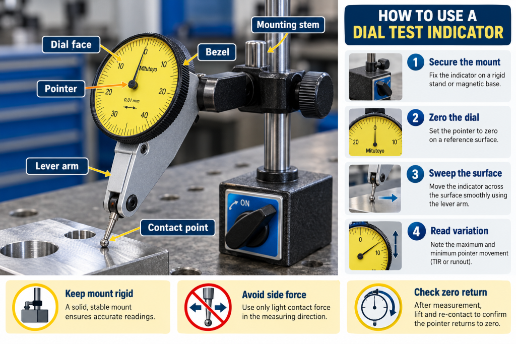
The contact point deserves special attention. Its length and design affect the indicator’s measuring behavior. Using an incorrect replacement stylus can introduce measurement errors, so check the manufacturer’s specifications before changing it.
How does a dial test indicator work?
When the contact point moves across a surface, the stylus pivots around its support. The internal mechanism converts that movement into pointer rotation.
The dial shows the change relative to the starting position. For example, if you zero the instrument on one point and the pointer later indicates a change of 0.03 mm (about 0.0012 in), the measured variation is approximately 0.03 mm.
The smallest marked division is the instrument’s graduation, often called its resolution in practical use. It is not the same as accuracy. Accuracy describes how close the reading is to the true value, and that depends on the instrument’s specifications, condition, and setup.
Dial Test Indicator vs. Plunger Dial Indicator
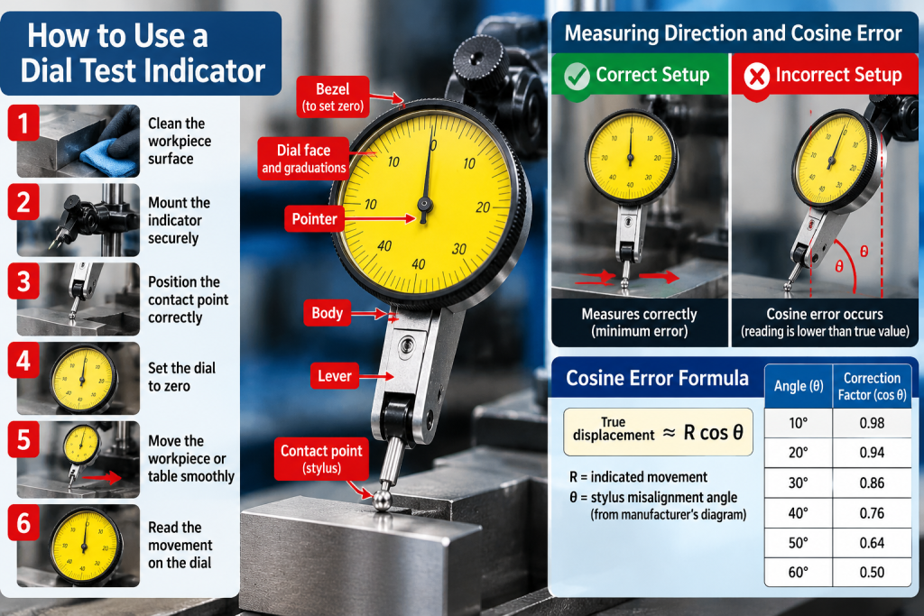
Both instruments display small movements on a dial, but their contact mechanisms work differently. Choosing between them depends on the direction of movement, access to the workpiece, and required measuring range.
| Feature | Dial test indicator | Plunger dial indicator |
|---|---|---|
| Measuring mechanism | A lever-type stylus pivots through an arc. | A plunger moves in and out along its axis. |
| Best use | Alignment, centering, surface sweeping, and restricted access. | Linear displacement, height changes, and measurements requiring more travel. |
| Measuring direction | Effective measuring direction depends on stylus geometry. | Plunger axis should align with the direction of movement. |
| Measuring range | Generally suited to small movements; model-dependent. | Available in a wide range of travel lengths. |
| Main setup concern | Stylus angle, contact-point length, and cosine error. | Plunger alignment, mounting rigidity, and side loading. |
| Typical mounting | Stem or dovetail holder, depending on design. | Stem, clamp, back lug, or other model-specific mounting. |
Choose a lever-type DTI when you need to sweep a surface, center a part, or reach a feature that is difficult to access with a straight plunger.
Choose a plunger dial indicator when the measurement involves straight-line travel and you can align the plunger with that movement.
Neither instrument is automatically more accurate than the other. Compare the specifications of the actual models, including graduation, measuring range, permissible indication error, and repeatability.
What Is a Dial Test Indicator Used For?
A DTI is especially useful when you need to detect small differences rather than measure a large dimension from scratch.
Common applications include:
For example, when aligning a vise on a milling machine, you can mount the DTI on the machine, place its contact point against a reference surface on the vise, and move the table along its travel. Changes on the dial show how much the surface deviates from the intended alignment.
A DTI is useful for these tasks because the lever-style contact point can reach surfaces that may be awkward to access with a plunger indicator.
How to Use a Dial Test Indicator
A reliable measurement starts with a rigid mount, a clean contact point, and correct alignment. Follow these general steps, and check your instrument’s manual for model-specific requirements.
- Clean the contact point and workpiece. Remove chips, dust, oil buildup, and other debris that could affect contact.
- Mount the indicator securely. Use a compatible holder or magnetic stand. Keep the setup rigid so the holder does not flex as the machine or workpiece moves.
- Position the contact point correctly. Align the indicator’s effective measuring direction with the movement you want to measure. Keep the stylus angle within the manufacturer’s recommended limits.
- Apply light contact. Move the indicator into contact with the surface and allow enough movement in the intended measuring range. Do not force the stylus against its travel limit.
- Set the reference. Place the contact point at the chosen datum, allow the reading to settle, and rotate the bezel to zero if the model supports this adjustment.
- Move the workpiece or indicator. Sweep the surface, move the machine table, or rotate the component as appropriate. Observe the direction and amount of pointer movement.
- Repeat the measurement. Return to the reference position and check whether the indicator returns to zero. Repeat the procedure to assess consistency.
For a lathe runout check, keep the spindle stopped while positioning or adjusting the instrument. Rotate the workpiece slowly by hand when the setup permits, and record the maximum and minimum readings.
The total indicated runout (TIR) is the difference between the maximum and minimum readings during the rotation.
For example, if the maximum reading is +0.03 mm and the minimum is −0.02 mm:
TIR = maximum reading − minimum reading
TIR = 0.03 − (−0.02) = 0.05 mm (approximately 0.0020 in).
This is the total indicated variation. It should not automatically be treated as the component’s pure eccentricity because the result can also reflect surface form, mounting, and other setup effects.
Dial Test Indicator Cosine Error: Formula and Examples
Cosine error occurs when the indicator’s effective measuring direction does not align with the direction of movement being measured. The resulting dial reading can differ from the true displacement.
The ideal setup minimizes this angular mismatch. Mitutoyo’s dial test indicator guidance explains how contact-point geometry affects the scale factor and provides approximate correction factors.
For an indicated movement (R) and a stylus misalignment angle (θ), the approximate corrected displacement is:
True displacement ≈ Rcosθ
Here, R is the indicated movement, and θ is the stylus’s deviation from its ideal measuring position, as defined by the manufacturer’s setup diagram. The cosine correction applies when this angle convention matches the instrument’s specified correction method. To minimize error, position the stylus according to the manufacturer’s instructions rather than estimating the angle from the indicator body’s orientation alone.
The following correction factors are rounded examples from Mitutoyo’s guidance.
| Misalignment angle | Approximate correction factor |
|---|---|
| 10° | 0.98 |
| 20° | 0.94 |
| 30° | 0.86 |
| 40° | 0.76 |
| 50° | 0.64 |
| 60° | 0.50 |
Use the specific correction guidance for your instrument when available. The rounded factors above are estimates, so results may differ slightly from calculations using an exact cosine.
Worked example 1: Small angular mismatch
Suppose the indicator shows 0.200 mm (approximately 0.0079 in), and the applicable misalignment angle is 10°.
- Take the indicated reading: 0.200 mm.
- Use the manufacturer’s rounded factor: 0.98.
- Calculate: 0.200 × 0.98 = 0.196 mm.
Approximate corrected displacement: 0.196 mm (0.0077 in).
Worked example 2: Larger angular mismatch
Suppose the indicated movement is again 0.200 mm, but the misalignment angle is 30°.
- Take the indicated reading: 0.200 mm.
- Use the manufacturer’s rounded factor: 0.86.
- Calculate: 0.200 × 0.86 = 0.172 mm.
Approximate corrected displacement: 0.172 mm (0.0068 in).
These examples show why setup matters. The second reading requires a much larger correction. Whenever possible, correct the setup instead of relying on mathematical compensation.
Common Mistakes and How to Check Accuracy
A DTI can produce repeatable-looking readings even when the setup is wrong. Check the following points before relying on a result.
- Using the wrong contact-point length: A replacement stylus with the wrong length can change the scale factor. Use the specified contact point for your model.
- Mounting the indicator loosely: A flexible holder can move independently of the workpiece and create false readings. Tighten the mount and check for unwanted movement.
- Ignoring angular alignment: An unsuitable stylus angle can introduce cosine error. Position the indicator according to the manufacturer’s diagram.
- Skipping the zero check: Dirt, drift, or a mechanical problem can prevent the pointer from returning to its starting position. Recheck zero before and after a measurement.
- Reading the dial from an angle: Looking at the dial from the side can cause parallax error. View the pointer and scale straight on.
- Applying excessive force: Pushing sideways on the stylus or forcing it beyond its normal travel can affect operation or damage the instrument. Use gentle contact and remain within the specified range.
- Confusing graduation with accuracy: A 0.001 mm graduation does not guarantee that every reading is accurate to 0.001 mm. Check the manufacturer’s permissible error and calibration information.
How can you check the instrument yourself?
Start by cleaning the contact point and testing its movement through the normal operating range. The pointer should move smoothly without sticking or jamming.
Next, set the instrument against a stable reference and check whether it returns to zero after repeated movements. If the task requires a known measurement value, compare the reading with a suitable calibrated reference or measurement standard.
Repeatability alone does not prove accuracy. If the indicator fails its checks, has been dropped, or gives inconsistent readings, remove it from precision work until it has been inspected or calibrated as appropriate.
Temperature can also affect measurements. For close-tolerance work, allow the instrument and workpiece to reach a stable temperature and follow the applicable measurement procedure.
Frequently Asked Questions
1. What does DTI stand for?
DTI stands for dial test indicator. It is a lever-type measuring instrument used to detect small changes in position, alignment, and surface variation.
2. What is the main difference between a dial test indicator and a plunger dial indicator?
A DTI uses a pivoting lever, while a plunger dial indicator uses a straight-moving plunger. A DTI is often more convenient for sweeping surfaces and reaching restricted areas, while a plunger indicator suits measurements along its axis of travel.
3. What is a dial test indicator used for on a milling machine?
It is commonly used to align a vise or workpiece, check surface variation, and inspect machine setup. The pointer shows deviations as the machine table or indicator moves.
4. How do you read a dial test indicator?
Identify the graduation value, set a reference point to zero if appropriate, and observe the pointer as the contact point moves. Interpret the reading according to the dial layout and the model’s measuring range.
5. What causes cosine error in a dial test indicator?
Cosine error occurs when the effective measuring direction is misaligned with the actual direction of movement. Correct the indicator’s geometry where possible, and apply a manufacturer-approved correction when necessary.
Final Thoughts
A dial test indicator is a practical precision tool for checking alignment, runout, and small changes in surface position. Its lever-style design makes it especially useful when access is limited or when you need to sweep a surface rather than measure a complete dimension.
For reliable results, use the correct contact point, mount the instrument rigidly, minimize cosine error, and check zero return and repeatability. Always verify the measuring range and permissible error against the specifications of your actual instrument.
