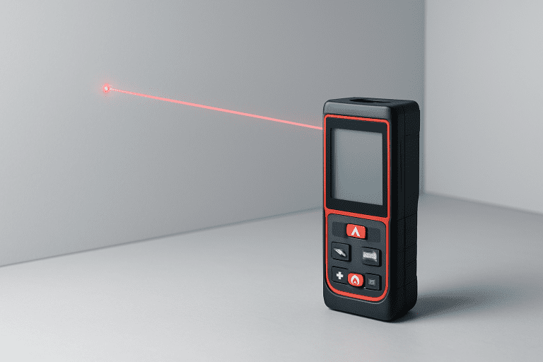
Think about how your phone knows how far away that wall is. Or how a self-driving car “sees” a pedestrian before it hits the brakes. The answer lies in laser technology—specifically, two main ways lasers measure distance.
Today, we’ll compare time-of-flight measurement and phase-shift measurement. These are the two dominant laser measurement methods used in everything from construction sites to autonomous vehicles. Understanding their differences matters. You’ll pick the right tool for your project. You’ll avoid costly mistakes. And you’ll understand the technology shaping modern measurement.
Both methods use light. Both calculate distance. But they work in completely different ways. Let’s dig into how they actually work—and which one you should use.
How Laser Distance Measurement Works: The Foundation
Before we compare, let’s establish the basics. All laser measurement systems rely on one simple principle: the speed of light never changes.
Light travels at roughly 300,000 kilometers per second. That’s incredibly fast. But it’s consistent. We can measure it. We can use it.
Here’s the fundamental formula that powers all laser ranging:
Distance = (Speed of Light × Time) ÷ 2
We divide by two because light makes a round trip. It goes out to the target and bounces back.
Here’s the catch: Light is so fast that even tiny time delays matter. To measure just one meter of distance, light takes only about 6.67 nanoseconds. That’s six billionths of a second. This is why laser measurement requires incredibly precise electronics.
Different laser ranging methods measure time and distance differently. That’s where time-of-flight and phase-shift diverge.
Why Light Works Better Than Other Methods
Laser light has advantages over regular light or radio waves. It’s focused into a narrow beam. It doesn’t scatter like a flashlight. The beam stays tight over long distances. This precision allows accurate distance calculations.
Near-infrared wavelengths are standard in laser measurement systems. They’re invisible to human eyes—that’s good for safety. They don’t interfere with visible light. And they bounce off most surfaces well.
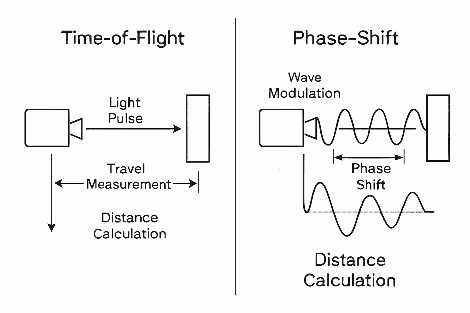
Time-of-Flight Measurement Explained
Time-of-flight measurement is straightforward. The name literally describes what it does: it measures how long a light pulse takes to travel.
How Time-of-Flight Laser Measurement Works
Here’s the process broken down into four simple steps:
Step 1: The Laser Emits a Pulse
Your scanner sends out a brief laser pulse. Think of it like a tiny lightning bolt. The pulse lasts only 10 to 15 nanoseconds. That’s incredibly short. But it’s intentional.
Step 2: The Pulse Travels
That laser pulse zooms toward your target at light speed. It keeps going until it hits something—a wall, a person, a building, anything.
Step 3: The Pulse Bounces Back
When the pulse hits your target, it reflects. The light bounces back toward the scanner. Most of it scatters in different directions. But some of it comes straight back.
Step 4: The System Calculates the Distance
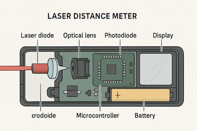
The scanner has a sensitive detector called a photodiode receiver. It catches the returning laser signal. The electronics measure exactly how long this round trip took. Then it does the math.
The Time-of-Flight Measurement Formula
Here’s how the calculation works:
Distance = (Speed of Light × Time Delay) ÷ 2
Let’s use a real example. Imagine light takes 100 nanoseconds to go out and back. Here’s the math:
The key insight: measuring time very precisely is everything in time-of-flight laser measurement. Timing circuits in your scanner must work at nanosecond speeds. Even one nanosecond of error creates about 15 centimeters of distance error.
Direct ToF vs Indirect ToF
There are actually two types of time-of-flight technology. Understanding the difference matters.
Direct ToF (dToF) measures the absolute travel time of each pulse. It uses specialized detectors called Single Photon Avalanche Detectors (SPADs). These catch individual photons. They measure the exact moment each photon arrives. This gives extremely accurate time measurements. Direct ToF is what you find in LiDAR systems for self-driving cars.
Indirect ToF (iToF) works differently. It modulates the laser with a pattern. Then it analyzes the pattern shift in the reflected light. It’s more complex mathematically but uses simpler, cheaper electronics. You’ll find iToF in smartphone cameras and robot navigation systems.
Advantages of Time-of-Flight Measurement
Here’s why time-of-flight has become so popular:
Longer Range – TOF vs phase-shift, the time-of-flight method wins for distance. Typical range extends from 100 meters to 6 kilometers. This makes it perfect for surveying large land areas. Autonomous vehicles can detect obstacles from 150 to 300 meters away. That’s enough time to react safely.
Simple Algorithm – The math is straightforward. Measure time, multiply by light speed, divide by two. Your microcontroller calculations stay simple. This means you need less processing power. Less power means lower costs.
Robust in Bad Conditions – Time-of-flight handles multipath interference better than competitors. If laser light bounces off multiple surfaces before reaching the detector, the system can still work. It measures the strongest, fastest returning signal.
Consistent Measurement Noise – The errors follow predictable patterns. This makes it easier to filter noise from real data. Your signal processing unit can remove obvious errors automatically.
True Angle Compensation – High-end time-of-flight scanners use dual-axis compensators. These adjust automatically if the scanner tilts during measurement. This feature keeps measurements accurate even on uneven ground.
Limitations of Time-of-Flight Measurement
But time-of-flight has real drawbacks too:
Poor Performance at Close Range – Here’s the paradox: time-of-flight struggles when targets are near. Measurement noise explodes below 30 meters. Why? The returning signal is too strong. It oversaturates the detector. The timing electronics can’t handle the strength. This makes it terrible for interior room capture.
Slower Data Collection – Typical TOF scanners capture 50,000 to 150,000 points per second. That sounds fast. But phase-shift systems capture over 1 million points per second. For large areas, the speed difference really matters.
High Power Requirements – Pulsed lasers need enormous bursts of energy. The emitted laser signal must be incredibly bright to travel far. This demands sophisticated power management. It generates heat. It increases system complexity.
Distance Degrades Signal Quality – As targets get farther away, the returned signal gets weaker. At extreme distances, the photodiode receiver struggles. This limits practical range in outdoor settings with ambient light.
Faster Electronics Costs Money – To achieve better accuracy, you need faster timing circuits. This equipment is expensive. Entry-level time-of-flight systems start around $35,000 to $80,000.
Phase-Shift Laser Measurement Explained
Phase-shift measurement takes a completely different approach. Instead of measuring time, it measures the shift in wave cycles.
How Phase-Shift Laser Measurement Works
Here’s how the phase-shift method operates:
Step 1: Emit a Modulated Signal
Instead of a short pulse, the laser emits a continuous wave laser signal. This signal is modulated—meaning its brightness goes up and down at a precise frequency. Imagine the light getting brighter and dimmer in a regular pattern. Typical modulation frequencies range from 1 to 100 megahertz.
Step 2: Travel to Target
This continuous wave modulation travels to your target. The brightness pattern stays consistent as it travels.
Step 3: Reflect Back
The reflected laser signal bounces back toward the scanner. Here’s the key: the pattern has shifted. The returning signal arrives slightly later. This creates a phase difference—the shift between the pattern you sent and the pattern you receive.
Step 4: Measure the Phase Difference
Your signal processing unit compares the transmitted pattern with the received pattern. It measures the phase shift in degrees or radians. This phase calculation reveals the distance.
The Phase-Shift Measurement Formula
Here’s the math:
Distance = (Speed of Light × Phase Difference) ÷ (4π × Modulation Frequency)
Let’s work through an example. Suppose:
The calculation: Distance = (3 × 10⁸ × π/2) ÷ (4π × 10 × 10⁶) = 3.75 meters
The key insight: changing the beam modulation frequency changes what distance you can measure. Higher frequencies give better resolution but shorter range. Lower frequencies extend range but lose precision.
Multi-Frequency Phase-Shift Technology
Here’s where phase-shift gets clever. There’s a problem called phase ambiguity. A single modulation frequency can’t tell the difference between 0 meters and 15 meters (if the wavelength is 30 meters). The phase looks identical.
Smart systems use multiple modulation frequencies. They might use 1 megahertz, then 10 megahertz, then 100 megahertz. By combining results from all three frequencies, the system resolves the ambiguity. It knows the exact distance, not just possibilities.
Advantages of Phase-Shift Measurement
Here’s why phase-shift technology has loyal fans:
Incredible Accuracy at Close Range – Phase-shift distance measurement explained simply: it’s precise. Typical accuracy is ±0.5 millimeter to ±2 millimeters. This is perfect for industrial measurement tools that need tight tolerances. Manufacturing quality control requires this level of accuracy.
Lightning-Fast Data Capture – Phase-shift systems capture over 1 million points per second. Some reach 3 million points per second. For large interior spaces, you scan in minutes instead of hours. Speed matters when you’re paying workers by the hour.
Lower Power Consumption – Continuous wave systems use less energy than pulsed systems. This means simpler power supplies. Smaller batteries. Cooler operation. Less thermal stress on components.
Great Indoors Performance – Phase-shift excels inside buildings and controlled environments. Range typically extends 100 to 200 meters. That’s perfect for building documentation. Perfect for reverse engineering complex parts. Perfect for interior layout capture.
Compact System Design – Continuous wave systems can be smaller and lighter. Phase-shift scanners often weigh less than ToF equivalents. This matters when you’re carrying equipment all day.
Real-Time Processing – Algorithms work fast. You can get immediate feedback on data quality. This helps you identify problems and rescan problem areas before leaving the site.
Lower Entry Cost – Entry-level phase-shift systems start around $12,000. Mid-range systems cost $35,000 to $50,000. That’s less than many ToF systems.
Limitations of Phase-Shift Measurement
But phase-shift has serious limitations too:
Limited Range – This is the biggest drawback. Typical effective range is 100 to 200 meters. Compare this to ToF systems reaching 6 kilometers. You simply cannot use phase-shift for long-distance surveying.
Spurious Points Create Noise – Phase-shift systems generate ghost points. These false measurements appear when the continuous wave modulation reflects off multiple surfaces. Your reflected laser signal gets confused. The signal processing unit misinterprets what’s happening. Post-processing cleanup becomes tedious.
Multipath Interference Problems – Complex scenes with many reflections fool phase-shift systems. Light bouncing off multiple surfaces creates ambiguous signals. This is common in warehouses, industrial facilities, and cluttered outdoor areas.
Phase Wrapping and Ambiguity – If distances exceed the wavelength, the phase wraps around. The system might return 5 meters when the true distance is 35 meters. Multi-frequency systems help, but problems still occur.
Sensitive to Environmental Changes – Moving people, changing lights, or dynamic scenes cause problems. Phase-shift measurement requires relatively static conditions. Moving objects create changing reflections that confuse the algorithms.
Temperature Sensitivity – The continuous wave modulation frequency drifts with temperature changes. A ±3 degree Celsius temperature shift can ruin measurements. You need temperature compensation or frequent recalibration.
Less Robust Tilt Compensation – Phase-shift systems usually rely on tilt sensors rather than true dual-axis measurement. This is less accurate than time-of-flight’s approach.
Dark Surface Problems – Black or highly absorptive surfaces don’t reflect enough light. The photodiode receiver picks up too little signal. Measurements fail on dark objects.
Head-to-Head Comparison: TOF vs Phase-Shift
Let’s put these side by side. Here’s what actually matters:
| Factor | Time-of-Flight | Phase-Shift |
|---|---|---|
| Measurement Range | 100 meters to 6 kilometers | 100 to 200 meters |
| Accuracy | ±2 to ±5 centimeters | ±0.5 to ±2 millimeters |
| Data Speed | 50,000 to 150,000 points/sec | 1 million+ points/sec |
| Close Range (under 30m) | Poor, very noisy | Excellent, very clean |
| Long Range (over 1km) | Excellent | Impossible |
| Power Use | High (pulsed lasers) | Lower (continuous wave) |
| Cost (Entry Level) | $35,000 to $80,000 | $12,000 to $45,000 |
| Robustness | Excellent outdoors | Needs controlled conditions |
| Multipath Handling | Handles well | Struggles significantly |
| Processing Complexity | Simple | Moderate to complex |
| Optimal Use | Long surveys, outdoors | Precision work, indoors |
The Range vs Accuracy Trade-Off
Here’s the fundamental reality: you cannot have both maximum range and maximum accuracy.
Time-of-flight achieves 6 kilometers of range but only ±2 to ±5 centimeters of accuracy. Phase-shift achieves ±0.5 millimeter accuracy but only 200 meters of range.
Why? Physics. Accurate phase calculation demands shorter wavelengths (higher frequencies). Short wavelengths have short unambiguous ranges. Long ranges require long wavelengths (lower frequencies). But long wavelengths reduce precision.
You choose what matters most for your project. Long-distance surveying? Choose time-of-flight. Precision manufacturing quality control? Choose phase-shift.
Speed vs Precision Trade-Off
Here’s another fundamental trade-off: faster scanning usually means less precision.
Phase-shift captures points 10 to 20 times faster than time-of-flight. But this speed comes from simpler calculations. Less processing time. Less averaging of multiple measurements. This contributes to phase-shift’s noise problems.
Time-of-flight captures fewer points per second but with more consistent accuracy. The algorithms have more time to ensure each measurement is solid.
Real-World Applications: Where Each Technology Shines
Where Time-of-Flight Laser Measurement Excels
Autonomous Vehicles
Self-driving cars use LiDAR systems with time-of-flight measurement. They need to see obstacles 150 to 300 meters away. That’s the distance required to stop safely at highway speeds. Phase-shift simply cannot reach that far. ToF is the only option.
Aerial Surveying
Drones equipped with time-of-flight scanners map terrain. A single flight can survey 50 to 80 hectares. The data gets combined into detailed maps. This is faster and cheaper than ground-based surveying.
Land Surveys
Surveyors use ToF scanners to map large construction sites. They capture terrain across multiple kilometers. They establish precise coordinate systems. They generate models for BIM integration.
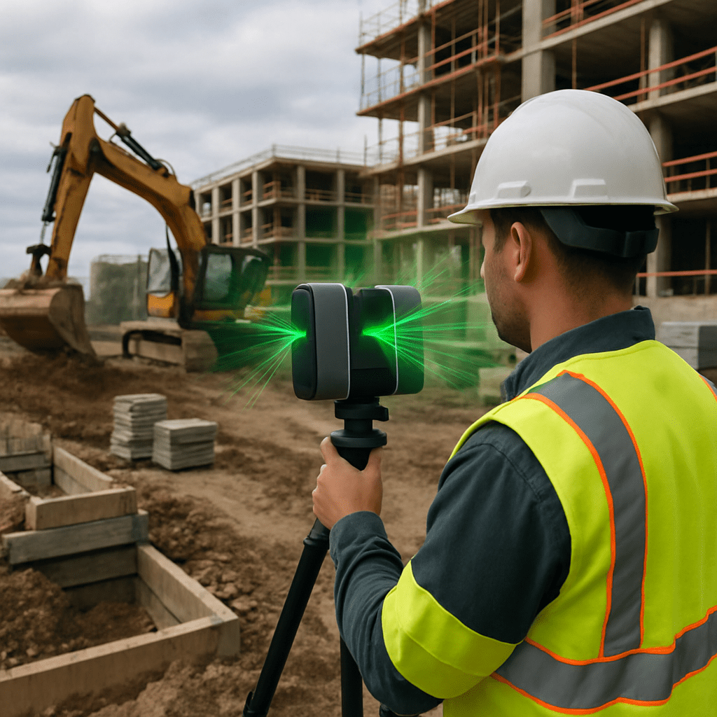
Real Customer Example:
A surveying firm needed to digitize a 2-square-kilometer construction site. Using time-of-flight scanners with 1-kilometer range, they completed scanning in 3 days. Accuracy of ±5 centimeters was perfect for BIM model creation. Manual surveying would have taken 2 weeks.
Where Phase-Shift Laser Measurement Excels
Industrial Metrology
Manufacturing facilities use phase-shift scanners for quality control. They measure engine blocks, aerospace components, and precision parts. They need ±0.5 millimeter accuracy. Time-of-flight cannot achieve this.

Reverse Engineering
Companies scan existing products to create digital models. They capture complex geometries of aircraft fuselage interiors, automotive body panels, and intricate machinery. Phase-shift’s speed and precision make this practical.
Architecture and Building Documentation
Interior designers capture room layouts and architectural details. They measure wall surfaces, ceiling heights, and door placements. They create models for renovation planning. Phase-shift’s ±2 millimeter accuracy suffices perfectly.
Construction As-Built Documentation
Contractors document what was actually built versus what was planned. They identify deviations and design changes. Phase-shift captures these details quickly during construction handoff.
Real Customer Example:
An automotive manufacturer needed to quality-check 500 precision components daily. Manual inspection took 8 hours per inspector per shift. Phase-shift scanners captured sub-millimeter variations in 2-minute scan cycles. Automated algorithms flagged defects. The system processed parts 40 times faster with better accuracy. It paid for itself in 6 months.
Hybrid Approaches: Combining Both Methods
Some advanced systems combine time-of-flight and phase-shift. Here’s how:
- Time-of-flight provides initial long-range scanning (up to 200+ meters)
- Phase-shift refines local areas with high precision
- Time-of-flight resolves phase ambiguity problems
- The result: extended range with millimeter accuracy
These hybrid systems are becoming mainstream. They overcome the limitations of both approaches.
Real Example:
A historic bridge inspection required both structural survey (200+ meter range) and joint detail capture (±2 millimeter precision). A hybrid system completed both requirements in a single deployment. This reduced inspection cost by 40% compared to using two separate systems.
Technical Factors That Affect Laser Measurement Accuracy
Several factors impact whether your measurements will be accurate or fail completely.
Environmental Conditions Matter
Temperature changes affect accuracy significantly. Here’s why:
Temperature Impact on Phase-Shift: Phase-shift systems need ±1 degree Celsius stability. Why? The continuous wave modulation frequency drifts with temperature. Even slight drift throws off phase calculations. ±3 degree Celsius changes can ruin data.
Temperature Impact on ToF: Time-of-flight tolerates ±2 degree Celsius changes. The electronics are more stable. Timing circuits have built-in temperature compensation.
Humidity Effects: Both methods work okay in normal humidity (20-80%). Above 80% humidity, air refractive index changes. Light bends slightly differently. This degrades accuracy for both approaches.
Wind Effects: Moving air doesn’t really affect laser signals. But wind moves your targets. If your target sways, measurements become inconsistent.
Sunlight and Ambient Light: This is where time-of-flight and phase-shift differ dramatically.
Time-of-flight tolerates sunlight. The system distinguishes real laser echoes from ambient light through timing analysis. Outdoor surveys are possible.
Phase-shift struggles with sunlight. Infrared interference overwhelms the system. Direct sunlight near the target causes failures. Phase-shift works outdoors only in overcast conditions or heavy shade.
Rain and Fog: Both methods degrade in rain or fog. Water droplets scatter laser light. The reflected signal weakens dramatically. Measurements pause until conditions improve.
Moving Targets: Time-of-flight handles moving objects better. It captures each point’s position at a specific instant. Phase-shift fails with dynamic scenes. Changing reflections confuse the phase detection algorithms.
How Surface Properties Affect Measurement
Different materials reflect laser light differently. This matters a lot.
Dark/Absorptive Surfaces (black rubber, deep paint, asphalt)
These absorb most laser energy. Reflection is weak. The photodiode receiver gets little signal. Measurements fail or become very noisy. Solution: Apply reflective targets or use higher laser power (within safety limits).
Shiny/Reflective Surfaces (mirrors, polished metal, glass)
These create specular reflection—the light bounces away at an angle. The beam doesn’t come straight back. The detector sees nothing. Solution: Use fiducial targets, adjust measurement angle, or reduce glare with polarization filters.
Transparent Materials (glass, plastic, water)
Light passes through instead of reflecting. The scanner measures what’s behind the transparent material, not the surface. Solution: Apply reflective targets to the surface you want to measure.
Matte Surfaces (standard paint, concrete, paper)
These are ideal. Diffuse reflection scatters light back evenly. The detector receives clean, strong signals. Measurements are accurate.
Textured Surfaces (rough concrete, fabric, tree bark)
Texture creates measurement noise. Multiple reflection angles cause interference. The system sees slightly different values from nearby points. Solution: Capture multiple passes and average results.
Color Variations: Darker colors absorb more laser light. Lighter colors reflect better. White surfaces are excellent for laser measurement. Black surfaces are poor. Red and blue absorb more infrared light than phase-shift systems prefer.
Equipment Selection and CostsAbout Us
Let’s talk real money. What does this equipment actually cost?
Price Ranges by Equipment Type
Terrestrial Static Scanners (Time-of-Flight)
Terrestrial Static Scanners (Phase-Shift)
Mobile/Handheld Scanners (Mostly Phase-Shift)
Drone-Mounted LiDAR (Time-of-Flight)
Automotive LiDAR (Integrated ToF)
Smartphone ToF/Phase-Shift Sensors
Laboratory Interferometers (Precision Phase-Shift)
Total Cost of Ownership Analysis
Buying equipment is just the beginning. Here’s a realistic cost breakdown for a construction surveying firm:
| Expense | Year 1 | Year 2 | Year 3 |
|---|---|---|---|
| Equipment | $65,000 | $0 | $0 |
| Software License (annual) | $5,000 | $5,000 | $5,000 |
| Initial Training | $2,000 | $0 | $0 |
| Field Labor (10 projects) | $15,000 | $15,000 | $15,000 |
| Processing Labor (10 projects) | $8,000 | $8,000 | $8,000 |
| Maintenance & Repairs | $2,000 | $2,500 | $2,500 |
| Calibration & Service | $1,000 | $1,000 | $1,000 |
| TOTAL | $98,000 | $31,500 | $31,500 |
3-Year Total: ~$161,000
Now compare to revenue. If each project brings $3,000 to $5,000 in service income and costs $1,500 to $2,000 to execute, your profit per project is $1,500 to $3,000. That’s 50-60 projects to break even.
Most surveying firms do 10-15 projects per year. Break-even happens in 4-6 years. But here’s the value: you charge premium rates for services others can’t offer. You differentiate from competitors. You win larger contracts.
How to Choose: Time-of-Flight vs Phase-Shift
Here’s a simple decision process:
Step 1: Determine Your Required Range
Step 2: Determine Your Accuracy Needs
Step 3: Check Your Environment
Step 4: Consider Your Speed Needs
Step 5: Review Your Budget
Selection Checklist
Before you buy:
□ Range requirement clearly documented? □ Accuracy specification matched to actual need? □ Environmental conditions assessed? □ Speed requirements defined? □ Budget allocated and approved? □ Software compatibility verified (CAD, BIM)? □ Support and training availability confirmed? □ Warranty and maintenance terms reviewed? □ Rental options evaluated before purchase? □ Team technical expertise level considered?
Common Mistakes to Avoid
Mistake 1: Buying More Range Than Needed
Some firms purchase 6-kilometer time-of-flight systems when 200-meter phase-shift would suffice. They pay triple for features they never use.
Mistake 2: Ignoring Environmental Factors
Buying phase-shift for outdoor construction projects without accounting for sun interference. The system fails in direct sunlight. Frustration and cost overruns follow.
Mistake 3: Underestimating Processing Time
Thinking faster scanning means faster project completion. Point cloud processing can take days even if scanning takes hours. Plan accordingly.
Mistake 4: Not Testing Equipment
Purchasing without trial on your actual materials. Different products perform differently on black paint, reflective metal, or transparent surfaces.
Mistake 5: Overlooking Software Integration
The system doesn’t integrate with your existing BIM or CAD workflows. You spend weeks converting data formats. Productivity stalls.
Mistake 6: Buying Premium Features You Won’t Use
Paying for 3 million points per second when you’ll never need more than 500,000 points per second. You’re throwing money away.
Mistake 7: Insufficient Training
Operators lack expertise. The system sits underutilized. You never unlock its real capabilities.
Mistake 8: Not Considering Hybrid Approaches
Attempting to solve a problem that needs both long range and high precision with a single method. A hybrid approach would work perfectly, but you didn’t know it existed.
Frequently Asked Questions
Q: Which method is objectively better—time-of-flight or phase-shift?
A: Neither is universally better. Time-of-flight wins for long distances and outdoor use. Phase-shift wins for precision and speed. Your specific needs determine the right choice. Use the selection checklist above to find your answer.
Q: Can phase-shift systems work outdoors?
A: Yes, but with limitations. Phase-shift works outdoors in overcast or shaded conditions. Direct sunlight causes failures. Strong infrared interference overwhelms the sensors. Time-of-flight is far more reliable outdoors. Some phase-shift systems include sun filters, but they reduce range further.
Q: Why does phase-shift create spurious points?
A: Multipath interference causes ghost points. When laser light bounces off multiple surfaces before reaching the detector, the signal processing unit misinterprets the data. It generates false measurements. Prevention: clean the scan area of reflective objects, use high-quality reflective targets, apply data filtering algorithms, and capture multiple angles.
Q: What accuracy should I actually expect at different distances?
A: Time-of-flight typically achieves ±2 centimeters at 100 meters, ±5 centimeters at 500 meters, and ±10 centimeters at 1 kilometer. Phase-shift maintains ±0.5 to ±2 millimeters at 50 meters but drops off quickly beyond 200 meters. Check manufacturer specifications for your specific model. Every scanner is different.
Q: How do I improve measurement accuracy in poor lighting?
A: For time-of-flight: increase laser power (within safety limits), use reflective targets, and reduce scanning speed for longer integration times. For phase-shift: use external lighting, reduce modulation frequency, and apply neutral density filters to reduce glare. Both benefit enormously from optimizing target placement.
Q: Can laser scanners measure moving objects?
A: Time-of-flight handles moving targets better. Phase-shift struggles. For objects in motion, use faster ToF systems, increase frame rate, or implement motion tracking algorithms. Autonomous vehicle LiDAR is ToF specifically because it must track moving pedestrians and vehicles.
Q: What’s the difference between direct ToF and indirect ToF?
A: Direct ToF measures absolute travel time using Single Photon Avalanche Detectors. It’s used in long-range LiDAR. Indirect ToF modulates the laser signal and analyzes pattern shifts. It’s compact and uses simpler electronics. dToF offers longer range. iToF offers better resolution in compact form. Smartphones typically use iToF. Self-driving cars use dToF.
Setting Up Your Laser Measurement System
Before You Start: Preparation Checklist
Environmental Assessment (15-30 minutes)
Equipment Preparation (15-20 minutes)
Site Calibration (20-30 minutes)
Scan Planning (30-45 minutes)
During Measurement: Best Practices
Maintain Stable Positioning: Don’t move the scanner between first pulse and complete reflection return.
Use Consistent Parameters: Keep same resolution, frame rate, and exposure across all scans.
Monitor Real-Time Feedback: Watch for saturation warnings or low confidence values.
Capture Multiple Overlaps: Aim for 30-40% overlap between scans for proper registration.
Document Everything: Record environmental conditions, scanner position, and anomalies.
Take Reference Photos: High-resolution photos provide essential context.
Verify Data Quality: Check histograms and spot-verify point placement in real time.
Manage Reflections: Remove reflective objects not being measured.
After Measurement: Data Processing
Step 1: Transfer and Backup (5-10 minutes)
Move raw point cloud data to processing computer. Create backup copies immediately.
Step 2: Point Cloud Registration (30 minutes to 2 hours)
Identify tie-points in multiple scans. Align scans to common coordinate system. Verify alignment error is under 5 millimeters.
Step 3: Point Cloud Cleaning (30 to 90 minutes)
Remove noise and outliers. Filter spurious points. Delete unreliable data. Manual cleanup using software tools.
Step 4: Data Validation (15-30 minutes)
Verify point density meets specifications. Check for gaps or missing areas. Cross-check measurements against known dimensions.
Step 5: Conversion and Export (10-20 minutes)
Convert to required format (LAS, PLY, E57, or CAD). Export with proper metadata. Generate density heatmaps.
Step 6: Quality Assurance (10-15 minutes)
Independent verification of key measurements. Compare to expected accuracy. Document any problems.
Processing Time Guidelines:
Advanced Topics: Future of Laser Measurement
Multi-Frequency Phase-Shift: Solving Ambiguity
Single-frequency phase-shift has a problem: phase ambiguity. The system can’t tell 0 meters from multiple wavelengths of distance. The phase looks identical.
Smart multi-frequency systems use 2 to 4 frequencies sequentially. A low frequency (1-5 megahertz) provides extended range. Higher frequencies (10-100 megahertz) provide precision. Combining results resolves ambiguity perfectly.
Result: Phase-shift range extends to 200+ meters with sub-millimeter accuracy.
Hybrid ToF/Phase-Shift Systems
Emerging technology combines both methods:
- Initial coarse ToF scan establishes distance range (0 to 1+ kilometer)
- Phase-shift algorithm determines precise distance within ambiguity window
- ToF resolves phase ambiguity, phase-shift provides precision
- Result: Extended range (to 1+ kilometer) with millimeter accuracy
This overcomes both approaches’ limitations simultaneously. Automotive LiDAR is moving toward hybrid systems. Surveying equipment will follow.
FMCW Laser Ranging: The Rising Alternative
FMCW (Frequency-Modulated Continuous Wave) is an alternative to phase-shift. The laser frequency is linearly swept. Reflected light shows frequency shift from the Doppler effect. Beat frequency measurements give direct range without phase wrapping.
Advantages: No phase ambiguity, simultaneous velocity measurement, extended operational range.
Disadvantages: Requires frequency-tunable laser (expensive), more complex hardware.
Status: Emerging in high-end applications but not yet mainstream.
Troubleshooting Common Measurement Problems
Time-of-Flight System Problems
| Problem | Cause | Solution |
|---|---|---|
| No signal or out of range | Target too far, low reflectivity | Move closer, use targets, improve lighting |
| Excessive noise | Close range, poor reflectivity | Move back, improve targets, increase power |
| Inconsistent measurements | Vibration, thermal drift, electrical interference | Stabilize setup, allow warm-up, shield from interference |
| Saturation errors | Close, bright target | Increase distance, reduce power, use neutral filter |
| Poor point cloud alignment | Insufficient overlaps, poor tie-points | Capture 40%+ overlap, improve targets, recalibrate |
| Range measurements off | Not calibrated, environmental changes | Recalibrate with known reference, verify temperature |
Phase-Shift System Problems
| Problem | Cause | Solution |
|---|---|---|
| Spurious ghost points | Multipath reflections | Remove reflective objects, use quality targets |
| Phase ambiguity errors | Unwrapping algorithm failure | Use multi-frequency, reduce distance, improve lighting |
| No data at distance | Range limit, low reflectivity | Reduce distance, improve reflectivity, adjust frequency |
| Noisy point cloud | Low signal, inadequate averaging | Increase averaging, extend integration time |
| Color/material failures | Black surfaces absorb light | Use targets, apply tape, measure reflection |
| Temperature drift | Thermal expansion, frequency shift | Allow 30-minute warm-up, monitor temperature |
| Sun interference | Infrared saturation | Move to shade, use sun shields, reduce integration |
General Troubleshooting Process
- Verify power and connections
- Clean optics
- Recalibrate with known distance reference
- Test on actual target material
- Adjust laser power, integration time, resolution
- Document working settings and conditions
- Rescan problem areas
If errors persist after recalibration, seek professional help. The issue is likely hardware.
Industry Standards and Compliance
Several international standards govern laser measurement:
ISO 8015 – Dimensional metrology fundamentals and tolerances ISO 13849-1 – Safety of measurement systems ISO/IEC Guide 98 – Uncertainty of measurement guidance ANSI B89.4.10 – American standard for laser trackers VDI 2634 – German standard for optical 3D metrology ASTM E3157 – Laser radar system calibration ASTM E2807 – In-process spectroscopy monitoring
These standards specify measurement uncertainty allowances, calibration frequency requirements, environmental conditions, and data validation procedures.
ISO 9001 certified manufacturers should provide traceability documentation. Check that equipment includes calibration certificates. Maintain calibration records for compliance.
Conclusion
Time-of-flight and phase-shift laser measurement represent two different philosophies. Time-of-flight says: “Let’s measure how long light takes to travel.” Phase-shift says: “Let’s measure how the light wave shifts.”
Neither is universally better. Each has strengths and weaknesses. Each works best in specific situations.
Time-of-flight wins for long-distance surveying and autonomous vehicles. It handles outdoor conditions and multipath interference. It measures kilometers with acceptable accuracy.
Phase-shift wins for precision work and indoor applications. It captures points faster. It achieves millimeter accuracy at close range. It costs less for short-range applications.
The best choice depends on your specific needs. Use the selection checklist in this article. Consider your required range, accuracy, environment, speed, and budget. Test equipment on your actual materials before buying.
Hybrid systems are emerging that overcome both approaches’ limitations. They combine long range with high precision. Watch for these innovations in surveying and automotive LiDAR markets.
Whether you choose time-of-flight or phase-shift laser measurement, you’re entering a world of precision that manual methods cannot match. You’ll work faster. You’ll measure more accurately. You’ll deliver better results.
The future of measurement is laser-based. Understanding these two core technologies positions you to make smart decisions—and to solve measurement problems you couldn’t solve before.