Angle of Approach: Optimizing Inclinometer Placement
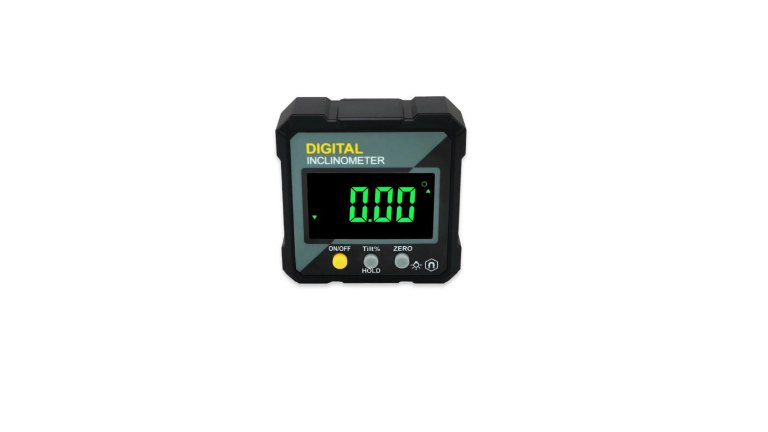
Inclinometers are versatile sensory devices that measure tilt, slope, and orientation relative to gravity. Based on MEMS accelerometers, electrolytic sensors, or force balance servos, they can resolve tilt changes under 0.1 degrees for precision applications. However, optimal inclinometer placement is vital to achieve usable accuracy and reliable data for infrastructure monitoring and industrial machinery control applications.
Careful orientation relative to the anticipated tilt direction, firm attachment to surfaces using adhesives/welding, and accounting for potential vibrations are essential for reliability. The closer they are mounted to the point of tilt occurrence, the greater the measurement precision. Distance from the center of rotation directly impacts sensitivity. They must also be placed to enable convenient calibration, data acquisition, and maintenance access without exposure to environmental interference. Expert testing informs suitable mounting spots.
With sound installation and calibration methods, inclinometers act as highly sensitive protractors – empowering you with instrumented feedback on equipment or structural tilt changes. This feedback guides corrective actions for precision construction and machinery maneuvering. The following sections discuss best practices for placement across typical applications.
Factors Influencing Inclinometer Placement
Optimal inclinometer placement requires evaluating operating conditions and functional objectives. Key factors include:
- Mounting Location: Installing inclinometers near areas with continual vibration risks inaccurate readings due to mounting base disturbance. Attaching them firmly to thicker mass structures lowers such interference. Temperature variations also impact readings if they are not compensated and calibrated accordingly. Any stray EM fields or radio waves from power cables or motors can corrupt sensor electronics. Accounting for such ambient interference via prior testing ensures valuable readings.
- Orientation Relative to Anticipated Tilt: Aligning the inclinometer axis perpendicular to the expected direction of tilt yields maximum sensitivity, allowing minor change detection. Contrast this with oblique orientation, where only tilt vector projections along the sensor axis are measured, losing resolution. For multifaceted equipment motion, dual-axis models help capture better directionality.
- Accessibility: Inclinometers must remain accessible post-installation for periodic inspection, re-calibration, data downloads, and battery/wiring maintenance needs. They have poor accessibility and are losing complete monitoring capability. Strategic mounting spots must be chosen via structural drawings,mock-ups, and service time estimates.
- Distance from Rotation Center: The greater the distance from the pivot/rotation axis, the higher the angular change for the same displacement, improving measurement sensitivity. Hence, distant mounting locations are preferred within functional range limits. This also lowers interference if the rotation center itself experiences disturbances.
- Examples: Effective placement for an overhead crane would involve attaching dual-axis sensors near the extreme ends of long boom sections at accessible joints. This maximizes tilt detection sensitivity, aiding early sway warnings. Sensors must be kept insulated from cutter drill vibration for tunneling machines while monitoring drive orientation. In dams, staggered multi-sensor arrays aid triangulation and early warning through directional tilt indications.
Mounting robust inclinometers optimized for the operating environs as distal as feasibly possible from anticipated rotation centers, correctly oriented perpendicular to tilt directions, assures maximum setup effectiveness. Expert testing and placement analysis prevent bad installations from losing massive monitoring capability.
Optimizing Placement for Structure Health Monitoring
For large civil structures like buildings, bridges, and dams, inclinometer placement requires a holistic approach—considering 3D geometry, operating conditions, past performance data, structural simulations, etc. Suitably oriented, calibrated, and shielded from noise, inclinometers can provide reliable indicators for developing subsurface issues.
Factors like daily solar heating cycles and foundation material properties that cause slight seasonal movement and tilt changes must be recorded during the initial years of regular operation. This establishes baseline signatures specific to the structure. Comparison of ongoing movements against these signatures then quantifies abnormal deviations indicative of instability, deterioration, or soil failures needing intervention.
For example, a gradual increase in upstream tilt over months in a concrete dam could signify water pressure destabilization of rock substrata requiring drain interventions. Missing this escalation can lead to catastrophic outcomes. Likewise, building subsidence is shown in compounding vertical foundation bolt strains. Dam and bridge piers exhibit abnormal transverse sway progression if foundations or joining sections fail under loading. Through such directional deformation analysis, even 0.1 to 0.5-degree progressive tilt changes detected can characterize the flaw – its position, growth rate, and root causes like erosion, cracks, etc. This makes health prognosis and preventative action possible.
Scale model studies often identify the best mounting locations. Civil structures undergo simulated aging via incremental loading while densely instrumented with micro-inclinometers. Resulting tilt signatures reveal optimal sensor positions on actual structures for maximum sensitivity to various failure modes. Thermal mapping also improves external interference isolation, enhancing the signal-to-noise ratio.
Effective integration of robust quality assured inclinometer hardware; more brilliant 24/7 cloud analytics software, with informed sensor placement driven by structural engineering inputs – promises substantial lifecycle benefits for critical infrastructure projects against catastrophe risks. The volume of condition data for accelerated pattern learning and flaw detection also rises dramatically through large-scale precision tilt monitoring via inclinometers.
Additional Applications and Placement Considerations
Beyond building and bridge monitoring, inclinometers have specialized placement needs across industries like mining, manufacturing, transport, and marine structures.
Continuous vibrations and intermittent shock loads require robust anchor mounting and data filtering in mining and tunnel boring. Thermal isolation and heating maintain sensor calibration integrity. Waterproof stainless housings work against corrosives. Easy instrument access eases periodic re-calibration needs down cramped shafts. Fireproof models suit underground coal sites. Placement priority lies in tracking drive orientation despite environmental noise.
For conveyor belt systems, redundant wireless sensor arrays with repeaters prove advantageous over hundreds of meters for early sloping detections, allowing automated height compensation. Low-maintenance battery replacements and remote analytics improve uptime. Gradual misalignment spotting prevents material run-off and jams.
In construction machinery, enclosed cab mountings must isolate sensors from damage while retaining visibility/control access. Positioning them near the machine periphery enhances early tip-over warnings by compounding the tilt rise captured. However, given its proximity to motor drives, electrical noise isolation merits priority.
For offshore oil platforms and vessels – salt fogs, gushing water breaches, and wave forces require specialized waterproof, pressure-sealed stainless enclosures with onboard heaters. Redundancy improves functional reliability. Tilt data assists crane load positioning on heaving decks. Automated multi-sensor data logging tracks stability integrity even during cyclones and floods.
In essence, context drives placement optimization. Encapsulating durable, sensitive MEMS tilt sensors, shielding from vibration, electrical noise, and environmental corrosion while retaining production line access, enables robust monitoring across facilities. An inclusive strategy covering mechanical, electrical, and data acquisition considerations is critical.
Achieving Precise Calibration and Useful Readings
The accuracy of the inclinometer-based tilt and slope data hinges greatly on meticulous calibration, which eliminates mounting disturbances. Expert installation guidelines cover optimal sensor settling periods, laser alignment checks, and interference isolation.
Precision calibration techniques use telescopic crosshairs with theodolite mounts for microscopic angle tuning. Electronic autocollimator-based methods employing digital signal processing also assure reliable alignment. Calibration tunnels free from ambient interference further improve the repeatability of these techniques.
Identifying sources of stray interference helps isolate valuable data. For example, AC magnetic fields from nearby electric grids can permeate sensor housings, producing signal distortion. Similar errors emerge if radio transmitters lie in proximity. Meticulous electromagnetic interference zoning of site areas during site survey informs suitable shielding or alternative mounting spot options.
Usable data validation requires both static and dynamic testing. Stationary multi-axis gravity readings must demonstrate stable vectors aligned to the proper level over extended periods after calibration. Dynamic response characterization analyzes the accuracy of angular velocity outputs across tilt motion ranges in contrast to high-fidelity reference from rate tables. This verifies appropriate amplification and filtering settings.
Adhering to system acceptance test procedures before commissioning brings reliability. It proves that repeatable, precise data is usable per tolerances like +/- 0.1 degree for equipment or infrastructure control needs. Investing in the proper calibration infrastructure and domain expertise prevents data issues in business-critical monitoring systems. Identifying interference sources also assures optimal field conditions for valid, consistent inclinometer data. This empowers significant efficiency and safety improvements across construction machinery, manufacturing units, and structural projects.
Conclusion
Optimizing inclinometer placement requires a holistic assessment of operating conditions, orientation needs, calibration access, and interference isolation unique to every use case. Costly inaccuracies emerge from casual inclinometer mounting without factoring in critical influences. Getting expert guidance for site surveys and installation best practices ensures usable precision. This enables full utilization of sensor capabilities – allowing infrastructure and machinery monitoring implementations to securely maximize safety, efficiency, and availability improvements over the long term. They are essential today because of their exponentially rising criticality, expertise, and diligence in inclinometer positioning.


