Ever stared at that volume knob on your old radio and wondered what magic happens inside? That little control knob holds one of electronics’ most clever inventions – the potentiometer. I’ve spent years working with these devices, and I’m excited to share how they work in simple terms.
Think of a potentiometer as a smart variable resistor that gives you precise control over voltage and current. It’s like having a dimmer switch for electricity itself.
What Is a Potentiometer?
A potentiometer is a three-terminal electronic component that acts as both a variable resistor and voltage divider. Picture a long piece of resistive material with a sliding contact that moves along its length.
The basic parts include:
When I first learned about potentiometers, my instructor compared them to a garden hose with a movable valve. Move the valve, change the water flow. Move the wiper, change the electrical resistance.
The potentiometer’s working principle relies on a simple fact: resistance changes as the path length changes. It’s that straightforward.
Fundamental Working Principle of Potentiometer
Here’s where things get interesting. The working principle of potentiometer centers on one key concept: voltage drop is proportional to length.
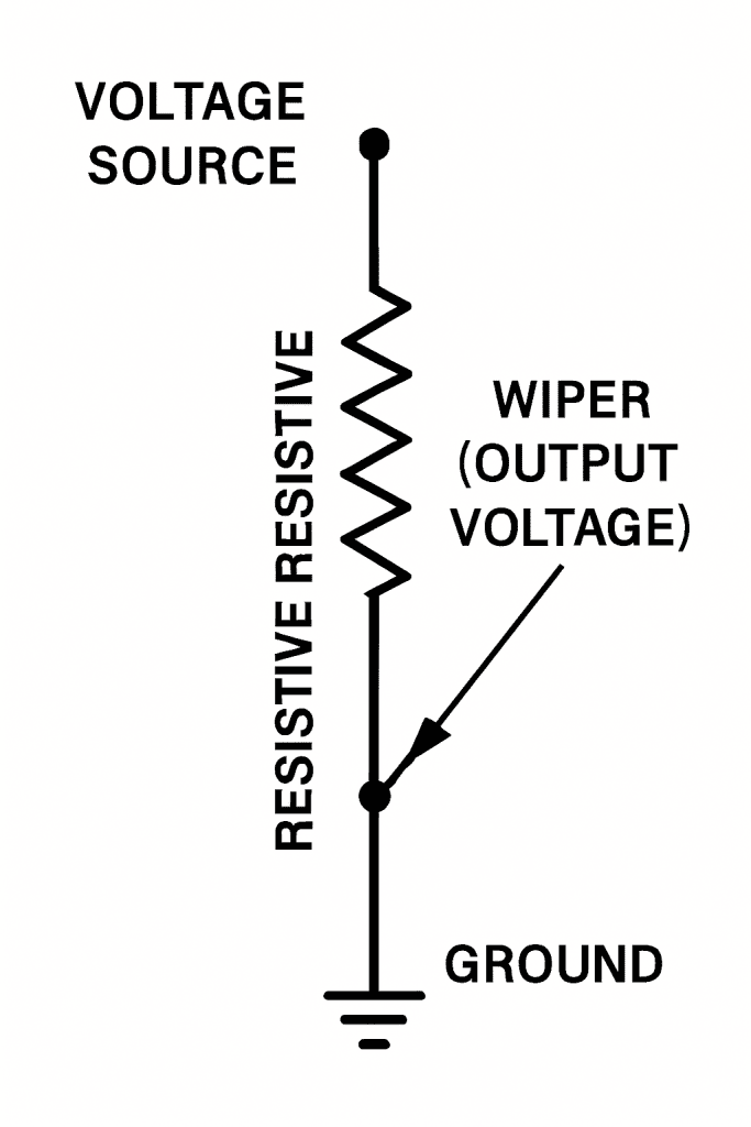
Infographic of potentiometer voltage divider operation
Imagine a uniform wire carrying current flow. As electricity travels through the wire, it loses voltage bit by bit. The longer the path, the bigger the voltage drop.
Ohm’s law governs this behavior. When current flows through resistance, voltage drops predictably. A potentiometer exploits this principle brilliantly.
The wiper position determines how much resistance sits between any two points. Move it closer to one end, and resistance decreases. Move it away, and resistance increases.
This variable resistance creates a voltage divider effect. You’re literally dividing the input voltage into smaller, controllable portions.
Construction and Key Components
Let me break down what’s inside a typical potentiometer:
The resistive element determines the total resistance range. Common values span from 100 ohms to several megohms.
How Does Potentiometer Work: Step-by-Step Process
Let me walk you through exactly how potentiometer works in a circuit:
Step 1: Apply Input Voltage Connect your voltage source across the two end terminals. This creates a uniform voltage gradient along the resistive element.
Step 2: Position the Wiper The wiper contact sits somewhere along the resistive element. Its position determines the output voltage ratio.
Step 3: Measure Output Take your output between the wiper terminal and either end terminal. You’ll get a fraction of the input voltage.
Step 4: Adjust as Needed Move the wiper to change the resistance ratio. This directly changes your output voltage.
Step 5: Maintain Circuit Balance The potentiometer maintains current flow while providing variable output. It’s like having an adjustable tap on your electrical circuit.
This potentiometer function makes it perfect for voltage divider applications. You get smooth, continuous control over output levels.
Potentiometer vs Voltmeter: Accuracy Comparison
Here’s something that surprised me early in my career. A potentiometer can measure voltage more accurately than many digital voltmeters.
|
Feature
|
Potentiometer
|
Voltmeter
|
|---|---|---|
|
Current Draw |
Zero at balance |
Always draws current |
|
Internal Resistance |
Infinite at null |
Fixed internal resistance |
|
Accuracy |
Extremely high |
Limited by internal design |
|
Speed |
Slow (manual) |
Fast (instant) |
|
Cost |
Moderate |
Varies widely |
The secret lies in null point detection. When properly balanced, a potentiometer draws no current from the circuit being measured. This eliminates loading effects that plague other measurement methods.
Voltmeters always draw some current. This current flow changes the circuit behavior slightly, introducing measurement errors.
Types of Potentiometers and Applications
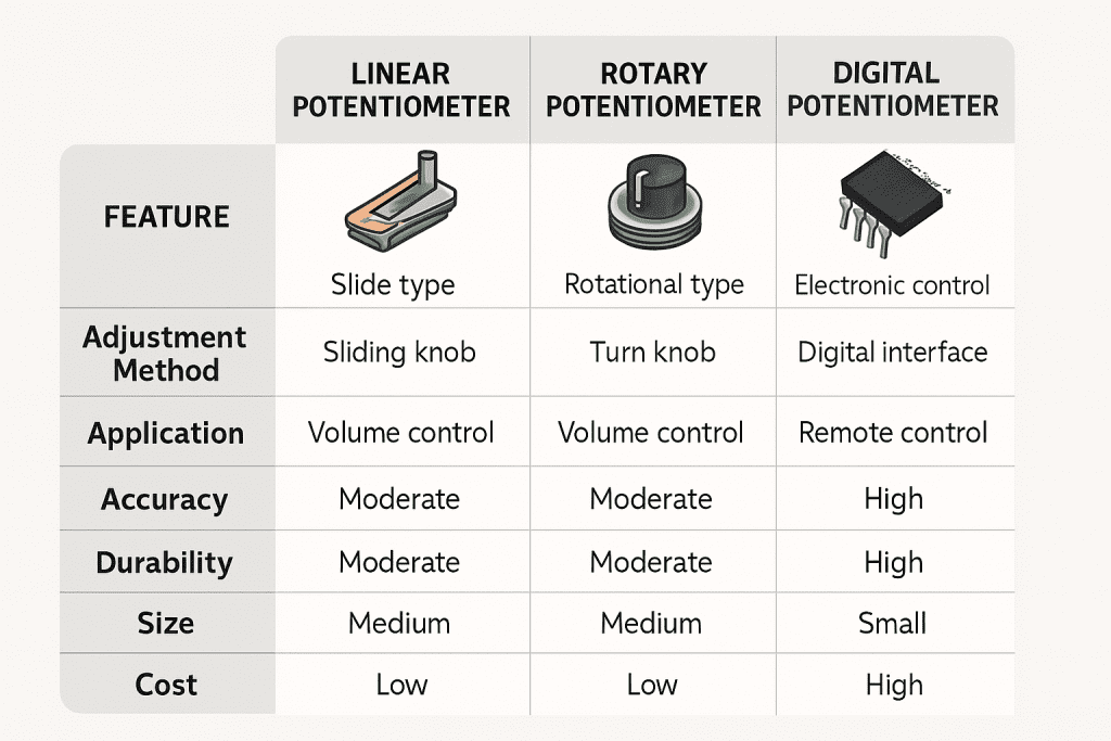
Comparative infographic of potentiometer types
Each type serves different needs in electronic components design.
Potentiometer Measurement Applications
I’ve used potentiometers in countless projects. Here are the most common applications:
The use of potentiometer in electronics spans nearly every field where precise control matters.
Advantages and Limitations of Potentiometer Operation
Let me give you the honest truth about potentiometers:
|
Advantages
|
Limitations |
|---|---|
|
High accuracy |
Mechanical wear over time |
|
Zero current draw |
Temperature sensitivity |
|
Simple construction |
Setup complexity |
|
Versatile applications |
Slower than digital methods |
|
Cost-effective |
Limited frequency response |
Despite limitations, the potentiometer basics remain sound for many applications.
Calibration and Null Point Detection Methods
Calibration requires careful attention to detail. Here’s my proven approach:
Step 1: Standard Setup Use a known voltage standard as a reference. Connect it to your potentiometer circuit properly.
Step 2: Null Detection Adjust the wiper position until your galvanometer reads zero. This indicates perfect balance.
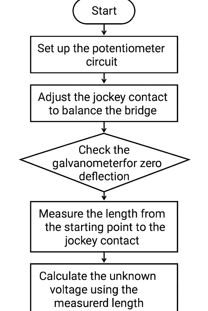
Flowchart of potentiometer measurement steps
Step 3: Sensitivity Check Make small adjustments to verify your null point. The reading should change predictably.
Step 4: Record Results. Document your settings for future reference. Good records save time later.
Step 5: Verify Repeatability Repeat measurements to ensure consistent results. This confirms your setup accuracy.
Real-World Engineering Applications
I’ve seen potentiometers work in amazing ways:
The analog vs digital potentiometers debate continues, but both have their place.
Common Problems and Troubleshooting Guide
After years of working with potentiometers, I’ve seen these issues repeatedly:
Frequently Asked Questions About Potentiometer Working
Q1. Why is potentiometer more accurate than voltmeter for EMF measurement?
A potentiometer draws zero current at the null point. This eliminates circuit loading effects that cause measurement errors in voltmeters. The result is incredibly accurate voltage measurements.
Q2. What materials are used in potentiometer construction and why?
Common materials include carbon (cheap), wire-wound resistance (precise), and conductive plastic (durable). Each material offers different trade-offs between cost, accuracy, and lifespan.
Q3. How do you determine the null point in potentiometer measurement?
Use a sensitive galvanometer connected between the unknown voltage and potentiometer output. Adjust the wiper until the galvanometer reads exactly zero. This indicates perfect voltage balance.
Q4. What factors affect potentiometer measurement accuracy?
Key factors include temperature stability, wiper contact quality, resistance uniformity, and external electrical interference. Proper calibration and maintenance minimize these effects.
Q5. Can potentiometer be used for both AC and DC measurements?
Standard potentiometers work best with DC voltages. AC measurements require special techniques because the wiper position must account for both magnitude and phase relationships.
Understanding how does the potentiometer work opens doors to countless electronic applications. Whether you’re building circuits, calibrating instruments, or just satisfying curiosity, these versatile electronic components deserve respect.
The next time you turn a volume control or adjust a dimmer switch, remember the elegant potentiometer working principle making it all possible. Simple concepts often create the most powerful solutions.