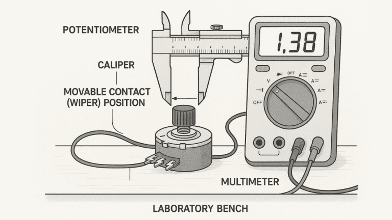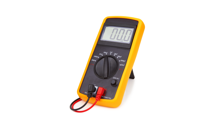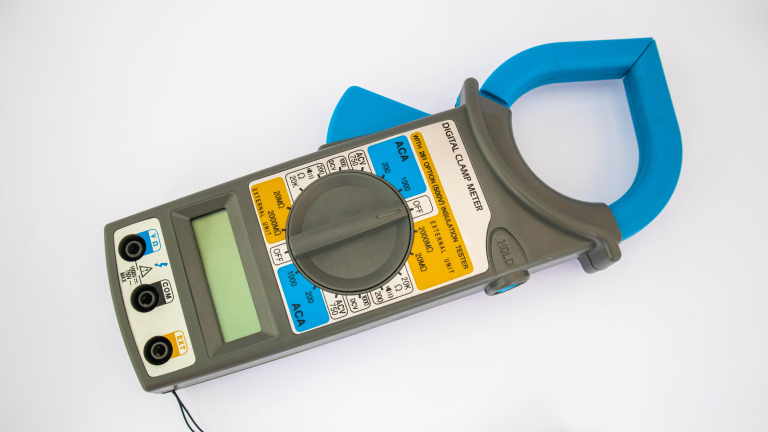
This guide provides a comprehensive introduction to using a multimeter for beginners. It will cover the basics of multimeters, including their components, types, and standard features. Additionally, it will delve into setting up the multimeter correctly, taking measurements for voltage, current, and resistance, and performing continuity tests. By the end of this guide, you will have a solid foundation in using a multimeter, enabling you to tackle basic electrical and electronics projects and troubleshooting tasks confidently.
Understanding the Multimeter
Understanding the Multimeter’s Components
The display is the primary interface that shows the measured values. Modern multimeters typically have a digital display that provides precise numerical readings. Some older models may feature an analog display with a moving needle that indicates the measurement on a scale.
The selector knob or dial is used to choose the desired measurement function (such as voltage, current, or resistance) and the appropriate range or scale for the measurement. It is crucial to set the correct function and range to obtain accurate readings and prevent damage to the multimeter.
The input ports, typically labeled with symbols like “V” for voltage,” A” for current, and “Ω” for resistance, are where you connect the test leads or probes to make measurements. Depending on the multimeter model, there may be separate ports for voltage, current, and resistance measurements or a single port that serves multiple purposes.
Buttons or switches on the multimeter allow you to control additional features like data hold, backlight, relative/zero mode, and more. Familiarizing yourself with the buttons and their functions will help you maximize your multimeter’s capabilities.
There are two main types of multimeters: analog and digital. Analog multimeters use a moving needle to display measurements on a calibrated scale, while digital multimeters provide precise numerical readings on a digital display. Digital multimeters are more common due to their increased accuracy, ease of use, and advanced features.
Most multimeters have standard features and functions, including voltage (AC and DC), current (AC and DC), resistance (resistance measurement), continuity testing, and sometimes capacitance and frequency measurements. Understanding how to use each function is essential for effective multimeter use.
By familiarizing yourself with a multimeter’s essential components and features, you will be better equipped to operate it safely and accurately, laying the foundation for successful electrical and electronic work.
Setting Up the Multimeter
Setting up the multimeter correctly is crucial for accurate measurements and safe operation. Choosing the suitable multimeter for your needs and following safety guidelines to protect yourself and your equipment is also essential.
- Choosing the Right Multimeter: When selecting a multimeter, consider the features and specifications that align with your intended use. A basic digital multimeter with voltage, current, and resistance measurement capabilities may suffice if you primarily work on household electrical systems. If you are involved in electronics repair or more advanced projects, look for a multimeter with additional features like capacitance (for measuring the ability of a component to store charge), frequency (for measuring the number of cycles per second in an electrical signal), and temperature measurement.
- Safety Precautions and Guidelines: Electrical safety should always be a top priority when using a multimeter. Only attempt measurements after disconnecting the power source from the circuit or device under test. Double-check that the multimeter is set to the correct function and range before taking any measurements. Avoid working on live circuits whenever possible, and use caution when measuring high voltages or currents.
- Understanding Settings and Ranges: Familiarize yourself with the multimeter’s selector knob or dial, which allows you to choose the desired measurement function (such as voltage, current, or resistance) and the appropriate range or scale. It is crucial to select the correct function to ensure accurate readings and prevent damage to the multimeter. Choosing the proper function can lead to correct measurements or harm the instrument.
- The range setting determines the maximum value the multimeter can measure for a given function. Please start with the highest range and gradually decrease it until you find the range that provides the most precise reading. For example, if you’re measuring a voltage of 5 volts, you should set the range to a value higher than 5 volts to ensure an accurate reading. Using an incorrect range can result in inaccurate measurements or damage to the multimeter in extreme cases.
Familiarizing Yourself with the User Manual: Every multimeter has a user manual that provides detailed information on its operation, features, and safety guidelines. Take the time to thoroughly read and understand the manual for your specific multimeter model. The manual will explain the different functions, settings, ranges, and special precautions or instructions for your particular multimeter.
By carefully selecting the suitable multimeter, following safety guidelines, understanding the settings and ranges, and consulting the user manual, you will be well-prepared to set up your multimeter correctly and take accurate measurements while minimizing risks.
Measuring Voltage
Voltage is a fundamental electrical quantity representing the potential difference between two points in an electrical circuit. Understanding and measuring voltage is essential for diagnosing and troubleshooting electrical systems, ensuring proper operation, and identifying potential issues.
- Setting up the Multimeter for Voltage Measurement: To measure voltage with a multimeter, start by rotating the selector knob or dial to the voltage measurement function, represented by the symbol “V” or a straight line with a wavy line on top. If your multimeter offers separate settings for AC and DC voltage measurement, choose the appropriate setting based on the type of voltage you are measuring.
- Measuring DC Voltage: To measure direct current (DC) voltage, connect the red probe or test lead to the positive (+) terminal of the voltage source and the black probe to the negative (-) terminal. If you’re unsure of the polarity, connecting the probes for DC voltage measurements is safe. The multimeter will display the measured voltage value with the correct polarity.
- Measuring AC Voltage: The polarity of the test leads does not matter for alternating current (AC) voltage measurement. Connect the red and black probes to the two points where you want to measure the voltage. The multimeter will display the AC voltage’s root mean square (RMS) value, representing the effective or equivalent DC voltage that would produce the same heating effect.
- Interpreting the Voltage Readings: Pay close attention to the multimeter’s display when measuring voltage. It will show the calculated voltage value, often accompanied by additional information like the unit of measurement (volts or millivolts) and any polarity indicators (+ or -) for DC voltage. If the measured voltage exceeds the selected range, the display may show an overload indication (such as “OL” or “1”), prompting you to switch to a higher range.
It is essential to interpret the voltage readings in the context of the circuit or device you are testing. Compare the measured values to the expected or specified voltages to identify discrepancies or potential issues. Deviations from expected values may indicate problems with components, connections, or power sources.
By understanding voltage, correctly setting up the multimeter, and accurately interpreting the voltage readings, you can diagnose and troubleshoot electrical systems effectively, ensuring their safe and proper operation.
- Measuring Current:
Current is the flow of electric charge through a circuit, and its measurement is crucial for understanding the behavior of electrical systems and identifying potential issues. Unlike voltage measurements, which can be taken parallel across a component, current measurements require the multimeter to be connected in series with the circuit or device under test.
- Setting up the Multimeter for Current Measurement: To measure current with a multimeter, rotate the selector knob or dial to the current measurement function, represented by the symbol “A” or a straight line with an arrow on top. If your multimeter offers separate settings for AC and DC measurement, choose the appropriate setting based on the type of current you are measuring.
- Measuring DC Current: To measure direct current (DC), disconnect the circuit or device from the power source and connect the multimeter in series with the circuit. Break the circuit at a convenient point and click the red probe to the positive (+) side of the break and the black probe to the negative (-) side. This will allow the current to flow through the multimeter’s internal shunt resistor, enabling the measurement of the current.
- Measuring AC Current: The polarity of the test leads does not matter for alternating current (AC) measurement. Break the circuit at a convenient point and connect the red and black probes in series with the circuit, ensuring that the current flows through the multimeter’s internal shunt resistor.
- Interpreting the Current Readings: When measuring current, pay close attention to the multimeter’s display, which will show the estimated present value, often accompanied by additional information like the unit of measurement (amperes or milliamperes) and any polarity indicators (+ or -) for DC. If the measured current exceeds the selected range, the display may show an overload indication, prompting you to switch to a higher range.
- Safety Considerations: Caution is essential when measuring current, as the multimeter is directly in the current flow path. Only attempt to measure current in a live circuit or device after first disconnecting it from the power source. Measuring current on a live circuit can be extremely dangerous and may damage the multimeter or cause personal injury.
By understanding the current, setting up the multimeter correctly, interpreting the contemporary readings accurately, and following safety guidelines, you can diagnose and troubleshoot electrical systems effectively while minimizing potential risks.
Measuring Resistance
Resistance is a fundamental property of electrical components that opposes the flow of electric current. Understanding and measuring resistance is crucial for evaluating the condition of components, troubleshooting circuits, and verifying correct operation.
- Setting up the Multimeter for Resistance Measurement: To measure resistance, rotate the selector knob or dial to the resistance measurement function, represented by the symbol “Ω” or a zigzag line. Ensure that the circuit or component you want to test is disconnected from any power source before proceeding.
- Measuring Resistance in Components and Circuits: Connect the red and black probes across the component or part of the circuit you want to test to measure resistance. Depending on the magnitude of the resistance, the multimeter will display the resistance value in ohms (Ω) or kilohms (kΩ).
- Interpreting Resistance Readings: When measuring resistance, compare the displayed value to the expected or specified resistance for the component or circuit. Deviations from the expected values may indicate faulty components, broken connections, or short circuits. It is essential to interpret the resistance readings in the context of the circuit or device you are testing.
Remember that resistance measurements should only be performed on unpowered circuits or components. Attempting to measure resistance in a live circuit can damage the multimeter and potentially create a safety hazard.
By understanding resistance, correctly setting up the multimeter, and accurately interpreting the resistance readings, you can evaluate the condition of electrical components and circuits, enabling effective troubleshooting and ensuring proper operation.
Continuity Testing
Continuity testing is a simple but helpful function that allows you to check for continuous electrical paths in circuits or components. It helps identify breaks, open circuits, or faulty connections.
To perform a continuity test, rotate the selector knob or dial to the continuity function, often represented by a symbol resembling a sound wave. Connect the red and black probes across the circuit or component you want to test.
If the multimeter detects a continuous electrical path, it will emit an audible tone or display a visual indication, confirming continuity. Conversely, if the path is broken or resistance is too high, the multimeter will remain silent or display a different indication, suggesting a lack of continuity.
Continuity testing is a quick and straightforward way to verify the integrity of electrical connections and paths, making it a valuable tool in basic troubleshooting and circuit analysis.
Troubleshooting with a Multimeter
A multimeter is a versatile tool for basic troubleshooting of electrical circuits and devices. It measures voltage, current, and resistance to identify common issues such as open circuits, short circuits, faulty components, and power supply problems.
To troubleshoot with a multimeter, visually inspect the circuit for any apparent signs of damage or loose connections. Then, the multimeter will be used to systematically measure voltages and currents at different points in the circuit, comparing the readings to expected values. Resistance measurements can help identify faulty components or breaks in wiring.
Techniques like signal tracing and isolation can help pinpoint the root cause of problems. By following the signal path and dividing the circuit into smaller sections, you can methodically narrow down the source of the issue and take appropriate corrective action.
Conclusion
In conclusion, this guide has covered the essential aspects of using a multimeter, including understanding its components, setting it up correctly, measuring voltage, current, and resistance, performing continuity tests, and using it for basic troubleshooting. Following the information and steps outlined here, you can confidently approach your electrical and electronics projects with a solid foundation in multimeter usage.
Remember, practice and experimentation are vital to mastering a multimeter. Do not hesitate to explore its capabilities further and apply what you have learned to real-world scenarios. Additionally, consider seeking additional resources, such as instructional videos, forums, and online communities, to expand your knowledge and skills.


